|
IOS Command/Syntax/Mode |
Purpose |
Notes |
|
Cisco Router Basic Operations |
||
|
enable |
Enter privileged mode |
Router# |
|
disable |
Return to user mode from privileged |
|
|
write erase |
Erase the configuration file that is currently present in NVRAM. |
|
|
reload |
Reboot device |
|
|
Logout or exit or quit |
Exit Router |
|
|
TAB |
Compleat Command |
|
|
configure terminal |
Enters global configuration mode |
Router(config)# |
|
hostname XXXXXXX |
Specifies the name for the router. |
|
|
interface Lo0 |
Set an interface (Lo0 : loopback (virtual interface, used for OSPF, BGP and RSRB), fa0/0 : fast, g0/0 gigabit ) slot/port |
Router(config-if)# |
|
ip address 192.168.1.1 255.255.255.0 |
To add an IP address to a interface |
|
|
no shutdown |
Enable an interface |
|
|
exit |
Exit from corrent session, step back |
|
|
router ospf 1 |
Go to router configuration mode. OSPF (Open Shortest path First) |
|
|
network 192.168.1.0 0.0.0.255 area 0 network 10.0.0.0 0.0.0.3 area 0 network 10.0.0.4 0.0.0.3 area 0 |
Network settings. Use multiple times for all network range. |
|
|
ping 192.168.3.1 |
Used in enable mode to diagnose basic network connectivity |
|
|
trace 192.168.3.1 |
To see the path that our ping packets take |
|
|
license boot module c2900 tech securityk9 yes exit write memory reload |
Change license to securityk9 on 2911 devices |
|
|
SECURITY STAGE 1: (close down any unnecessary default services) |
||
|
no cdp run |
Disable CDP for the whole router |
|
|
no tcp-small-servers no udp-small-servers |
Disable small services (disabled by default IOS 12.0 and later) |
Order important |
|
no service finger no ip finger |
Disable finger services (user lookup) |
|
|
no ip http server |
Disable HTTP server |
|
|
no ip bootp server |
Disable BOOTP (other server can’t boot from this one) |
|
|
no service config no boot network |
Disable autoloading (loading configuration from TFTP server) |
|
|
no ip source-route |
Disable packets specify their own routes |
|
|
no snmp-server |
Disable remote query and configuration |
|
|
no ip domain-lookup |
Disable DNS if not in use !!! |
|
|
service tcp-keepalives-in service tcp-keepalives-out |
Disable TCP Keepalives service |
|
|
Interface-based default services - (interface fa0/0 – (substitute g0/0 on a 2911)) |
||
|
ntp disable |
Disable NTP time server. |
|
|
no ip proxy-arp |
Disable Proxy ARP, unless acting as LAN “bridge” |
|
|
no ip directed-broadcast |
Disable Directed Broadcast |
|
|
no ip unreachable |
Disable to prevent mapping network. Used on all interface connected to untrusted network. |
|
|
no ip mask-reply |
Disable reply an IP address mask. |
|
|
no ip redirect |
Disable ICMP redirect. Used on all interface connected to untrusted network. |
|
|
SECURITY STAGE 2: Applying passwords and password encryption to different router access components and modes. |
||
|
banner motd "THIS ROUTER SHOULD BE ACCESSED BY AUTHORISED PERSONNEL ONLY !" |
Applying banner |
global configuration mode: |
|
line console 0 password cisco login exit |
Set a console (user mode) password to cisco. |
|
|
line vty 0 4 password cisco login exit |
Set a telnet password (telnet or ssh) |
|
|
line aux 0 password cisco login exit |
This password will secure the aux port. |
|
|
enable secret class |
Set the enable secret password to “class” to privileged mode. |
|
|
service password-encryption |
Encrypt passwords. |
|
|
SECURITY STAGE 3: Encrypting routing protocols - in this case OSPF (Open Shortest Path First). |
||
|
router ospf 1 area 0 authentication message-digest |
Area 0 can have an encrypted password. |
|
|
interface Lo0 ip ospf message-digest-key 1 md5 grape interface fa0/0 ip ospf message-digest-key 1 md5 grape |
Set password to interfaces. Have to do on all loopback and other interfaces. |
|
|
Basic Firewalls – Access Control (Packet Filters) vs NAT/PAT (basic stateful) |
||
|
|
||
|
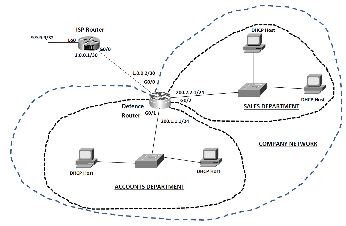
USING PACKET FILTERING AS A FIREWALL |
||
|
The “ISP” Router |
||
|
enable configure terminal hostname ISP interface g0/0 ip address 1.0.0.1 255.255.255.252 no shutdown exit interface lo0 ip address 9.9.9.9 255.255.255.255 exit ip route 200.0.0.0 255.0.0.0 1.0.0.2 exit |
Enter privileged mode Enter global configuration mode Name the router “ISP” Access g0/0 configuration mode Assign IP address Activate the interface Exit to global configuration mode Access lo0 configuration mode Assign a pingable address Exit to global configuration mode Add a static route towards our company network |
|
|
The “Defence” router |
||
|
enable configure terminal hostname Defence |
|
|
|
interface g0/0 ip address 1.0.0.2 255.255.255.252 ip access-group 1 in |
Apply access list “1” filter inbound. |
|
|
ip access-group 1 out no shutdown exit |
Apply access list “1” filter outbound too! |
|
|
interface g0/1 ip address 200.1.1.1 255.255.255.0 ip access-group 101 in no shutdown exit |
Apply access list “101” filter inbound. |
|
|
interface g0/2 ip address 200.2.2.1 255.255.255.0 no shutdown exit ip route 0.0.0.0 0.0.0.0 1.0.0.1 |
Create default router to outside world. |
|
|
ip dhcp excluded-address 200.1.1.1 ip dhcp excluded-address 200.2.2.1 |
Make sure DHCP does not hand out 200.1.1.1 & 200.2.2.1 |
|
|
ip dhcp pool Sales network 200.1.1.0 255.255.255.0 default-router 200.1.1.1 exit |
Create DHCP service for Sales Set DHCP address range Set default gateway address |
|
|
ip dhcp pool Accounts network 200.2.2.0 255.255.255.0 default-router 200.2.2.1 exit |
Create DHCP service for Accounts along the same lines as for Sales |
|
|
access-list 1 deny any |
Set up access-list 1 to deny all traffic. |
|
|
access-list 101 deny tcp 200.1.1.0 0.0.0.255 200.2.2.0 0.0.0.255 eq www |
Access list 101 set up to deny any web traffic or ICMP between the two networks of PCs. All other traffic is permitted. |
|
|
access-list 101 deny icmp 200.1.1.0 0.0.0.255 200.2.2.0 0.0.0.255 |
|
|
|
access-list 101 permit ip any any |
|
|
|
|
|
|
|
|
|
|
|
|
||
|
USING NAT AND PAT INSTEAD OF PACKET FILTERS – BASICS OF STATEFUL FIREWALLS |
||
|
The “ISP” Router: |
|
|
|
no ip route 200.0.0.0 255.0.0.0 1.0.0.2 |
remove the static route we needed earlier. (global configuration mode) |
|
|
write memory |
|
|
|
The “Defence” router: |
|
|
|
no access-list 1 no access-list 101 |
Removes the IP access list “1” Removes the Extended IP access list “101” |
|
|
interface g0/0 no ip access-group 1 in no ip access-group 1 out |
Remove the interface applications for access list 1 |
|
|
interface g0/1 no ip access-group 101 in |
Remove the interface application for access list 101 |
|
|
access-list 1 permit 200.2.2.0 0.0.0.255 |
Adds a new access list “1” to permit the 200.2.2.0 network to be translated by NAT. |
|
|
ip nat inside source list 1 interface g0/0 overload |
Activate NAT so that those permitted in access list “1” are “translated” via NAT using the exterior interface address. The “overload” keyword tells it to also switch PAT on. |
|
|
interface g0/0 ip nat outside |
Tell the router that g0/0 is the “outside” NAT interface (unfriendly). |
|
|
interface g0/1 ip nat inside interface g0/2 ip nat inside |
Tell the router that the other two interfaces are on the “inside” and are friendly. |
|
|
|
||
|
GRE Tunnelling & Virtual Private Networks |
||
|
|
||
|
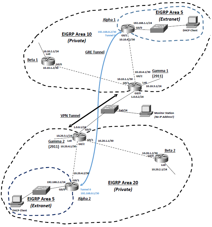
Task 1: Creating an extranet with another company using GRE. |
||
|
Basic Configuration for Gamma1: enable configure terminal hostname Gamma1 interface lo0 ip address 10.10.3.1 255.255.255.0 interface g0/0 ip address 1.0.0.2 255.255.255.0 no shutdown interface g0/1 ip address 10.10.1.1 255.255.255.252 no shutdown interface g0/2 ip address 10.10.4.1 255.255.255.252 no shutdown exit ip route 10.20.4.0 255.255.255.252 1.0.0.1 router eigrp 10 no auto-summary redistribute static network 10.0.0.0 exit exit |
Basic Configuration for Gamma2: enable configure terminal hostname Gamma2 interface lo0 ip address 10.20.3.1 255.255.255.0 interface g0/0 ip address 1.0.0.1 255.255.255.252 no shutdown interface g0/1 ip address 10.20.1.1 255.255.255.252 no shutdown interface g0/2 ip address 10.20.4.1 255.255.255.252 no shutdown exit ip route 10.10.4.0 255.255.255.252 1.0.0.2 router eigrp 20 no auto-summary redistribute static network 10.0.0.0 exit exit |
|
|
Basic Configuration for Alpha 1: enable configure terminal hostname Alpha1 interface g0/0 ip address 192.168.1.1 255.255.255.0 no shutdown interface g0/1 ip address 10.10.4.2 255.255.255.252 no shutdown exit ip dhcp excluded-address 192.168.1.1 ip dhcp pool Alpha1 network 192.168.1.0 255.255.255.0 default-router 192.168.1.1 exit router eigrp 10 no auto-summary network 10.0.0.0 exit router eigrp 5 no auto-summary network 192.168.1.0 exit |
Basic Configuration for Alpha 2: enable configure terminal hostname Alpha2 interface g0/0 ip address 192.168.2.1 255.255.255.0 no shutdown interface g0/1 ip address 10.20.4.2 255.255.255.252 no shutdown exit ip dhcp excluded-address 192.168.2.1 ip dhcp pool Alpha2 network 192.168.2.0 255.255.255.0 default-router 192.168.2.1 exit router eigrp 20 no auto-summary network 10.0.0.0 exit router eigrp 5 no auto-summary network 192.168.2.0 exit |
|
|
Basic Configuration for Beta1: enable configure terminal hostname Beta1 interface lo0 ip address 10.10.2.1 255.255.255.0 interface g0/0 ip address 10.10.1.2 255.255.255.252 no shutdown exit router eigrp 10 no auto-summary network 10.0.0.0 exit exit |
Basic Configuration for Beta2: enable configure terminal hostname Beta2 interface lo0 ip address 10.20.2.1 255.255.255.0 interface g0/0 ip address 10.20.1.2 255.255.255.252 no shutdown exit router eigrp 20 no auto-summary network 10.0.0.0 exit exit |
|
|
Task 2: Adding the GRE tunnel to link up the two extranet areas. |
||
|
GRE Configuration for Alpha1: interface tunnel 0 ip address 192.168.0.2 255.255.255.252 tunnel source g0/1 tunnel destination 10.20.4.2 exit router eigrp 5 network 192.168.0.0 exit |
GRE Configuration for Alpha 2: interface tunnel 0 ip address 192.168.0.1 255.255.255.252 tunnel source g0/1 tunnel destination 10.10.4.2 exit router eigrp 5 network 192.168.0.0 exit |
The Alpha routers need to add the following commands to link the areas together. |
|
Task 3: Monitoring our traffic. (Configuration for Monitoring Switch) |
||
|
enable configure terminal monitor session 1 source interface fa0/1 – 23 monitor session 1 destination interface fa0/24 exit exit |
What this configuration does, is it tells the switch to take a snapshot of every single frame it gets on ports 1 – 23, and then send them out of port fa0/24. |
|
|
Task 4: Now let’s secure the link across the “outside” using a Site-to-Site VPN tunnel. This needs to be set up on the two Gamma routers. |
||
|
VPN (IKE Phase 1) Configuration on Gamma 1: crypto isakmp enable crypto isakmp policy 1 authentication pre-share encryption des hash md5 group 1 lifetime 34000 exit crypto isakmp key grapefruit address 1.0.0.1 |
VPN (IKE Phase 1) Configuration on Gamma2: crypto isakmp enable crypto isakmp policy 1 authentication pre-share encryption des hash md5 group 1 lifetime 34000 exit crypto isakmp key grapefruit address 1.0.0.2 |
|
|
access-list 100 permit gre any any access-list 100 permit ip any any |
We now need to define interesting traffic using an extended IP access list on both routers. We will make sure of it by encrypting everything that tries to go across the link, so on both routers we need: Gamma1 and Gamma2 |
|
|
VPN (IKE Phase 2) Configuration on Gamma 1: crypto ipsec transform-set OurVPN esp-3des esp-sha-hmac mode tunnel exit crypto map Gamma1 1 ipsec-isakmp match address 100 set peer 1.0.0.1 set transform-set OurVPN set pfs group2 set security-association lifetime seconds 44000 exit |
VPN (IKE Phase 2) Configuration on Gamma 2: crypto ipsec transform-set OurVPN esp-3des esp-sha-hmac mode tunnel exit crypto map Gamma2 1 ipsec-isakmp match address 100 set peer 1.0.0.2 set transform-set OurVPN set pfs group2 set security-association lifetime seconds 44000 exit |
We need to set up IKE Phase 2 and get the IPSec protocol running for the “inner tunnel” which will actually protect our company network data. |
|
To Apply the VPN tunnel to Gamma 1: interface g0/0 crypto map Gamma1 exit |
To Apply the VPN tunnel to Gamma 2: interface g0/0 crypto map Gamma2 exit |
|
|
Useful Debugging Commands for Privileged mode for VPNs: |
||
|
show crypto isakmp sa |
display information about IKE phase 1 tunnel status |
|
|
show crypto ipsec sa |
display information about IKE phase 2 tunnel status |
|
|
|
||
|
|
||
|
|
||
|
GRE over VPN Tunnel Exercise With Added Zone-based Firewall |
||
|
Task 1: Setting up the basic network including the GRE tunnels between the areas. Task 2:Set up the VPN tunnel between the two Border routers. Task 3: Implementing a Zone-based Firewall to protect the Border routers. |
||
|
zone security INSIDE exit zone security OUTSIDE exit |
First we need to tell the router it is going to be a firewall device by specifying two firewall zones for the network – an “outside” low security zone and an “inside” high security zone. ( Global Configuration Mode )
|
|
|
access-list 105 permit gre host 10.10.4.2 host 10.20.4.2 access-list 106 permit gre host 10.20.4.2 host 10.10.4.2 |
For The Upper Area: (Gemma 1) |
|
|
access-list 105 permit gre host 10.20.4.2 host 10.10.4.2 access-list 106 permit gre host 10.10.4.2 host 10.20.4.2 |
For The Lower Area: (Gemma 2) |
|
|
class-map type inspect INSIDENETWORK-CLMAP match access-group 105 exit |
Now these access lists are set we now need to specify something called a “class-map” which is used on routers to “group” network traffic into a “class” for ease of handling so we shall set up and “inspection” classmap which is for handling security. |
|
|
class-map type inspect OUTSIDENETWORK-CLMAP match access-group 106 exit |
|
|
|
policy-map type inspect INSIDE2OUTSIDE-PMAP class type inspect INSIDENETWORK-CLMAP inspect exit exit |
Then we now need to set up a policy map which allows us to instruct the router how to act on our new traffic class maps. |
|
|
policy-map type inspect OUTSIDE2INSIDE-PMAP class type inspect OUTSIDENETWORK-CLMAP inspect exit exit |
|
|
|
zone-pair security IN2OUT-ZPAIR source INSIDE destination OUTSIDE service-policy type inspect INSIDE2OUTSIDE-PMAP exit |
Now we need to implement these policy maps as a zone firewall “pair”.
|
|
|
zone-pair security OUT2IN-ZPAIR source OUTSIDE destination INSIDE service-policy type inspect OUTSIDE2INSIDE-PMAP exit |
|
|
|
interface g0/0 zone-member security OUTSIDE exit |
And finally tell the router which interfaces should be judged as “outside” unfriendly interfaces and which ones are “inside” friendly interfaces:
|
|
|
interface g0/1 zone-member security INSIDE exit |
· Your firewall should be operational and your sites should now be able to ping as normal. · Try the following diagnostic command from privileged mode to ensure that your firewall is configured correctly:
show policy-map type inspect zone-pair sessions
|
|
|
|
||
|
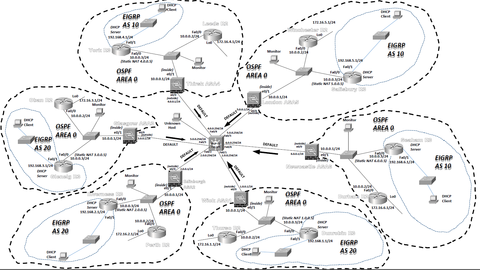
Introduction to dedicated firewall appliances using the Cisco Adaptive Security Appliance (ASA 5510) |
||
|
|
||
|
Sample diagram |
||
|
Stage 1: Making sure our ASA is free of a previous configuration. (enable, write erase, reload) Stage 2: Basic interface setup. |
||
|
interface e0/0 |
Fast Ethernet ports on an ASA are “e x/x” instead of “fa x/x” |
|
|
nameif outside |
Interfaces on ASA devices must have names. At least one must be called “outside” and at least one other must be called “inside” – other interfaces can be named as you see fit. |
|
|
ip address 1.0.0.1 255.255.255.0 |
|
|
|
security-level 0 |
Security levels range from 0 to 100. 0 is the least secure – hence it is assigned to the “unfriendly” outside interface. The “friendly” inside interface defaults to 100 – i.e. the most secure. |
|
|
no shutdown exit |
Wake up the interface – just like a router. The ASA won’t bother telling you it is up though.
|
|
|
interface e0/1 nameif inside ip address 10.0.0.1 255.255.255.0 security-level 100 no shutdown exit |
The full configuration for the “inside” interface.
|
|
|
show nameif |
Useful debugging command to list interfaces. |
|
|
Stage 3: Setting up NAT and Static NAT |
||
|
We are going to use dynamic NAT to allow access beyond the ASA to the outside world for “inside hosts” and also use static NAT to allow a connection from the outside world to the GRE tunnel end point routers so that these tunnels can connect. |
||
|
object network WickNAT subnet 10.0.0.0 255.255.255.0 nat (inside,outside) dynamic interface exit |
Entering the first “object” command, opens up a new configuration mode. The “subnet” command tells the ASA that this object is concerned with the subnet 10.0.0.0/24. The “nat” command tells the ASA that this subnet is to be used for allowing dynamic NAT and the “interface” keyword indicates that the exterior interface IP address should be used AND PAT should also be turned on. |
|
|
object network GREConnect host 10.0.0.3 nat (inside,outside) static 1.0.0.5 exit |
As you can see the object names are completely up to you – however I have used names which remind us of what their purpose is. It’s easier to debug configurations if you do this! The “host” command sets the particular “inside” interface that will be accessible from “outside” Then the “nat” command sets the IP address which it is mapped to on the “outside” |
|
|
show xlate show nat |
Useful debugging commands to show what NAT has taken place, and for showing NAT settings.
|
|
|
Stage 4: To get the ASA involved in OSPF. (The following is the configuration on the WickASA1 device) |
||
|
route outside 0.0.0.0 0.0.0.0 1.0.0.254 |
Default route (that’s the 0.0.0.0 0.0.0.0 part of the command). Is available via the “outside” interface via the next hop address which in this case is the layer 3 switch connection at 1.0.0.254. |
|
|
router ospf 1 network 10.0.0.0 255.255.255.0 area 0 default-information originate exit |
Very much like the commands you have used on the routers. Except of course for the lack of a wildcard mask!
|
|
|
show route |
This command shows the routing table. |
|
|
Stage 5: To be able to test the network connectivity |
||
|
access-list OUT-IN permit gre any host 10.0.0.3 access-list OUT-IN permit icmp any host 10.0.0.3 |
We have created an access list called OUT-IN – the first line which allows the GRE traffic to pass through bound for 10.0.0.3. The second rule allows pings for testing connectivity to the same address. |
|
|
access-group OUT-IN in interface outside |
This command actually applies the access list to the “outside” interface in an “inbound” direction. |
|
|
Stage 6: Verify network connectivity. Stage 7: Adding VPN tunnels with ASAs. (Global Config Mode on WickASA1) |
||
|
crypto ikev1 policy 1 authentication pre-share encryption 3DES group 2 hash md5 lifetime 50000 exit |
Creating our IKE Phase 1 policy (apart from the first command, it all looks like the router IOS commands). |
|
|
crypto ikev1 enable outside |
Turn on the IKEv1 tunnel capability on the “outside” interface. |
|
|
crypto ipsec ikev1 transform-set ToEdinburgh esp-des esp-sha-hmac |
Start IKE Phase 2 to use SHA hashing and DES encryption for ESP. |
|
|
access-list TOEDINBURGH permit gre any any access-list TOEDINBURGH permit ip any any |
Set the “interesting” traffic to go over the VPN. |
|
|
tunnel-group 2.0.0.1 type ipsec-l2l tunnel-group 2.0.0.1 ipsec-attributes ikev1 pre-shared-key Pear exit |
Declare the key for the IKE phase one and designate the VPN “site-to-site” (l2l).
|
|
|
crypto map Wick 1 match address TOEDINBURGH crypto map Wick 1 set peer 2.0.0.1 crypto map Wick 1 set ikev1 transform-set ToEdinburgh crypto map Wick 1 set pfs group1 crypto map Wick 1 set security-association lifetime seconds 86400 |
Create a crypto map for Wick for IKE phase 2 and give it its characteristics line by line. |
|
|
crypto isakmp nat-traversal 3600 |
Allow IKE to pass through the NAT wall for one hour. |
|
|
crypto map Wick interface outside |
Activate the VPN tunnel we have created on the “outside” interface. |
|
|
Useful debugging commands for ASAs: |
||
|
show conn |
Show connections. |
|
|
show xlate |
Show NAT translations. |
|
|
show run string |
Show a particular part of the configuration file. |
|
|
show route |
Show the ASA routing table. |
|
|
show nameif |
Show the interfaces and their names. |
|
|
show nat |
Show nat configuration details. |
|
|
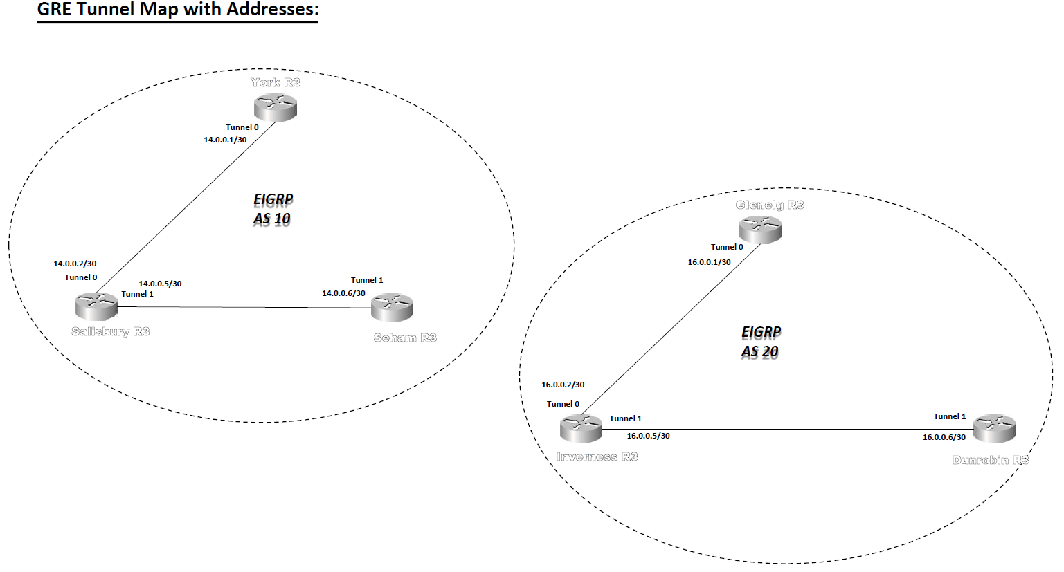
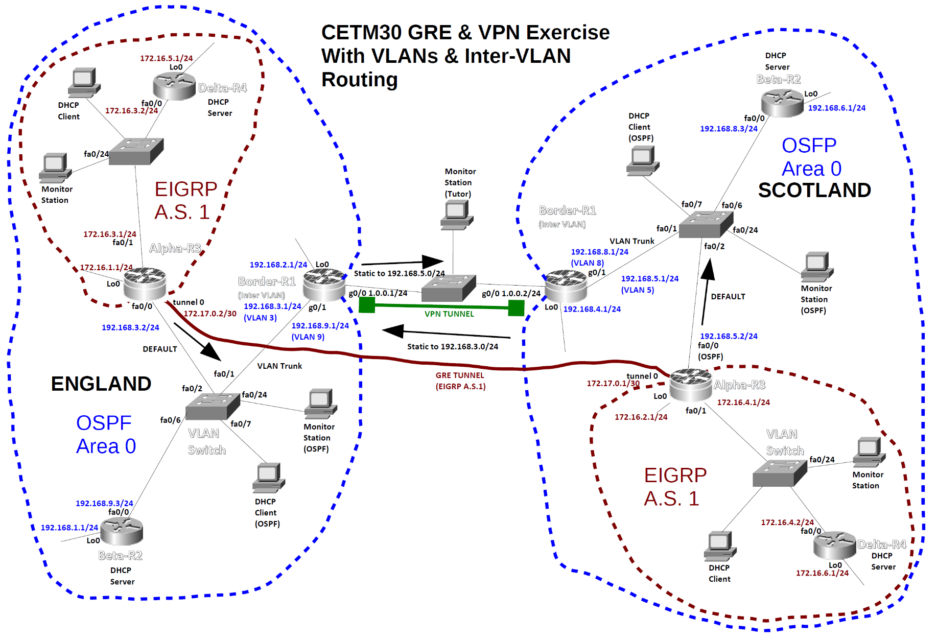
GRE & VPN Network With Added VLAN Configuration on the OSPF Area Switches |
||
|
|
||
|
Configuration for the England Switch |
||
|
enable |
|
|
|
vlan database |
enter VLAN configuration mode |
|
|
vlan 3 name Secret |
create VLAN 3 with name “Secret” |
|
|
vlan 9 name Ordinary |
create VLAN 9 with name “Ordinary” |
|
|
exit |
exit and save VLAN information |
|
|
configure terminal |
|
|
|
interface fa0/1 |
|
|
|
switchport trunk encapsulation dot1q |
|
|
|
switchport mode trunk |
turn g0/1 into a trunk for all VLANs |
|
|
interface range fa0/2 – 5 |
enter configuration mode for ints 1-5 |
|
|
switchport mode access |
make sure they are access ports |
|
|
switchport access vlan 3 |
place them in VLAN 3 |
|
|
interface range fa0/6 – 10 |
|
|
|
switchport mode access |
place these ones in VLAN 9 |
|
|
switchport access vlan 9 |
|
|
|
exit |
|
|
|
monitor session 1 source interface fa0/2 – 10 |
for use by monitoring station on |
|
|
monitor session 1 destination interface fa0/24 |
interface fa0/24 |
|
|
exit |
|
|
|
Configuration for the England Border-R1 Router (you will need to add VPN commands) |
||
|
enable |
|
|
|
hostname Border-R1 |
|
|
|
interface g0/0 |
|
|
|
ip address 1.0.0.1 255.255.255.0 |
|
|
|
no shutdown |
|
|
|
interface lo0 |
|
|
|
ip address 192.168.2.1 255.255.255.0 |
|
|
|
interface g0/1.3 |
create a sub-interface on g0/1 |
|
|
encapsulation dot1q 3 |
place it in VLAN 3 |
|
|
ip address 192.168.3.1 255.255.255.0 |
give it an IP address |
|
|
interface g0/1.9 |
create another sub-interface |
|
|
encapsulation dot1q 9 |
put it in VLAN 9 |
|
|
ip address 192.168.9.1 |
give it an IP address |
|
|
255.255.255.0 |
activate physical interface |
|
|
interface g0/1 |
and all sub-interfaces. |
|
|
no shutdown |
|
|
|
exit |
|
|
|
ip route 192.168.5.2 255.255.255.255 1.0.0.2 |
|
|
|
router ospf 1 |
N.B. No advert for secret VLAN! |
|
|
net 192.168.9.0 0.0.0.255 area 0 |
|
|
|
net 192.168.2.0 0.0.0.255 area 0 |
|
|
|
redistribute static subnets |
|
|
|
exit |
|
|
|
Configuration for the Scotland Switch |
||
|
enable |
|
|
|
vlan database |
|
|
|
vlan 8 name Ordinary |
|
|
|
vlan 5 name Secret |
|
|
|
exit |
|
|
|
configure terminal |
|
|
|
interface fa0/1 |
|
|
|
switchport trunk encapsulation dot1q |
|
|
|
switchport mode trunk |
|
|
|
interface range fa0/2 – 5 |
|
|
|
switchport mode access |
|
|
|
switchport access vlan 5 |
|
|
|
interface range fa0/6 – 10 |
|
|
|
switchport mode access |
|
|
|
switchport access vlan 8 |
|
|
|
exit |
|
|
|
monitor session 1 source interface fa0/2 – 10 |
|
|
|
monitor session 1 destination interface fa0/24 |
|
|
|
exit |
|
|
|
Configuration for the Scotland Border-R1 Router (Add VPN commands later) |
||
|
enable |
|
|
|
hostname Border-R1 |
|
|
|
interface g0/0 |
|
|
|
ip address 1.0.0.2 255.255.255.0 |
|
|
|
no shutdown |
|
|
|
interface lo0 |
|
|
|
ip address 192.168.4.1 255.255.255.0 |
|
|
|
interface g0/1.5 |
|
|
|
encapsulation dot1q 5 |
|
|
|
ip address 192.168.5.1 255.255.255.0 |
|
|
|
interface g0/1.8 |
|
|
|
encapsulation dot1q 8 |
|
|
|
ip address 192.168.8.1 255.255.255.0 |
|
|
|
interface g0/1 |
|
|
|
no shutdown |
|
|
|
exit |
|
|
|
ip route 192.168.3.2 255.255.255.255 1.0.0.1 |
|
|
|
router ospf 1 |
|
|
|
net 192.168.8.0 0.0.0.255 area 0 |
|
|
|
net 192.168.4.0 0.0.0.255 area 0 |
|
|
|
redistribute static subnets |
|
|
|
exit |
|
|
|
|
||
|
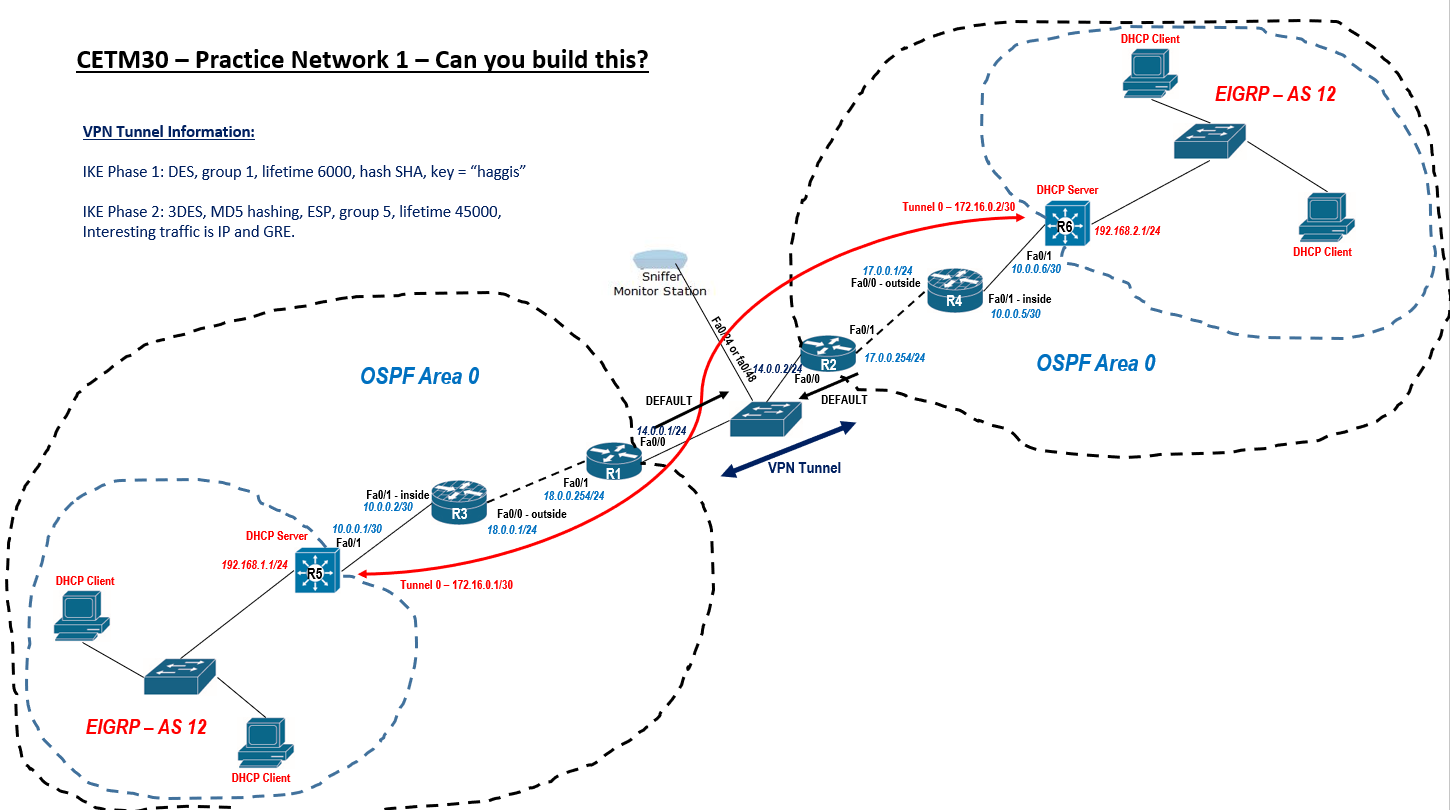
Practice Network 1 – Layer 3 Switch Configurations |
||
|
Layer 3 switch half EIGRP and half OSPF area (firewall) |
||
|
Complete Configuration for R5 (please adapt this for configuring R6) |
||
|
enable |
|
|
|
configure terminal |
|
|
|
ip routing |
turn on the routing engine |
|
|
interface fa0/1 |
|
|
|
no switchport |
turn fa0/1 into a routing port |
|
|
ip address 10.0.0.1 255.255.255.252 |
|
|
|
exit |
no shutdown missing as ports on by default |
|
|
vlan 20 |
create a VLAN to support EIGRP network |
|
|
name EIGRPHosting |
|
|
|
exit |
|
|
|
interface vlan 20 |
|
|
|
ip address 192.168.1.1 255.255.255.0 |
give the VLAN an IP address |
|
|
exit |
all assigned ports will have this address |
|
|
interface range fa0/2 – 24 |
assign VLAN to all other ports |
|
|
switchport mode access |
|
|
|
switchport access vlan 20 |
|
|
|
exit |
|
|
|
interface tunnel 0 |
|
|
|
ip address 172.16.0.1 255.255.255.252 |
|
|
|
tunnel source fa0/1 |
|
|
|
tunnel destination 10.0.0.6 |
ip address at the other end. |
|
|
exit |
|
|
|
router eigrp 12 |
|
|
|
no auto-summary |
|
|
|
network 192.168.1.0 |
route for VLAN 20 address range |
|
|
network 172.16.0.0 |
route for GRE tunnel |
|
|
exit |
|
|
|
router ospf 1 |
|
|
|
network 10.0.0.0 0.0.0.3 area 0 |
route towards outside private network. |
|
|
exit |
|
|
|
exit |
|
|
|
Addendum |
You will need to set all the ports on the two EIGRP switches to VLAN 20 to stop some rather annoying error messages: |
|
|
enable |
|
|
|
configure terminal |
|
|
|
vlan 20 |
|
|
|
name EIGRPHosting |
|
|
|
exit |
|
|
|
interface range fa0/1 – 24 |
(or 48) |
|
|
switchport mode access |
|
|
|
switchport access vlan 20 |
|
|
|
exit |
|
|
|
|
||
|
|
||
|
Cisco Router Show Commands |
||
|
show version |
View version information |
|
|
show running-config |
View current configuration (DRAM) |
|
|
show startup-config |
View startup configuration (NVRAM) |
|
|
show flash |
Show IOS file and flash space |
|
|
show log |
Shows all logs that the router has in its memory |
|
|
show interface e0 |
View the interface status of interface e0 |
|
|
show ip interfaces brief |
Overview all interfaces on the router |
|
|
show controllers 0 |
View type of serial cable on s0 (note the space between the 's' and the '0') |
|
|
show cdp neighbor |
Display a summary of connected cdp devices |
|
|
show cdp entry * |
Display detailed information on all devices |
|
|
show ip protocols |
Display current routing protocols |
|
|
show ip route |
Display IP routing table |
|
|
show access-lists |
Display access lists, this includes the number of displayed matches |
|
|
show isdn status |
Check the router can see the ISDN switch |
|
|
show frame-relay pvc |
Check a Frame Relay PVC connections |
|
|
show frame-relay lmi |
show lmi traffic stats |
|
|
show frame-relay map |
Display the frame inverse ARP table |
|
|
show crypto isakmp sa |
Display information about IKE phase 1 tunnel status |
|
|
show crypto ipsec sa |
Display information about IKE phase 2 tunnel status |
|
|
show policy-map type inspect zone-pair sessions |
Diagnostic command from privileged mode to ensure that your firewall is configured correctly |
|
|
show xlate show nat |
Useful debugging commands to show what NAT has taken place, and for showing NAT settings. |
|
|
show route |
This command shows the routing table. |
|
|
|
||
|
Assignment Practice |
||
|
Task 1 Establish a GRE tunnel between R2 and R3 – use the diagram for any necessary IP information. |
||
|
R2 router setting |
|
|
|
enable |
|
|
|
conf term |
|
|
|
int tunnel 0 |
|
|
|
ip add 8.0.0.1 255.255.255.252 |
|
|
|
tunnel source fa0/1 |
|
|
|
tunnel destination 10.0.0.2 |
port ip address on destination |
|
|
exit |
|
|
|
router eigrp 1 |
|
|
|
network 8.0.0.0 |
|
|
|
exit |
|
|
|
R3 router setting |
|
|
|
enable |
|
|
|
conf term |
|
|
|
int tunnel 0 |
|
|
|
ip add 8.0.0.2 255.255.255.252 |
|
|
|
tunnel source fa0/1 |
|
|
|
tunnel destination 172.16.10.2 |
port ip address on destination |
|
|
exit |
|
|
|
router eigrp 1 |
|
|
|
network 8.0.0.0 |
|
|
|
exit |
|
|
|
|
|
|
|
Task 2 Add OSPF authentication between routers R2 and R1 – use the keyword Jupiter |
||
|
R2 router setting |
|
|
|
enable |
|
|
|
conf term |
|
|
|
router ospf 1 |
check network settings if not sure set properly |
|
|
area 0 authentication message-digest |
|
|
|
int fa0/1 ip ospf message-digest-key 1 md5 Jupiter |
Must set all used ports. VLAN port too. Check ports on Activity result. |
|
|
exit |
|
|
|
R1 router setting |
|
|
|
enable |
|
|
|
conf term |
|
|
|
router ospf 1 |
check network settings if not sure set properly |
|
|
area 0 authentication message-digest |
|
|
|
int fa0/1 ip ospf message-digest-key 1 md5 Jupiter int fa0/1.10 ip ospf message-digest-key 1 md5 Jupiter |
Must set all used ports. VLAN port too. Check ports on Activity result. |
|
|
exit |
|
|
|
|
|
|
|
Task 3 Add a VPN tunnel using the parameters on the top-left of the diagram between R1 and “Firewall” – Use access list 101 for interesting traffic. |
||
|
R1 router IKE Phase 1 setting |
|
|
|
crypto isakmp enable |
|
|
|
crypto isakmp policy 1 |
|
|
|
authentication pre-share |
|
|
|
encryption des |
|
|
|
hash md5 |
|
|
|
group 2 |
|
|
|
lifetime 74000 |
|
|
|
exit |
|
|
|
crypto isakmp key fish address 200.1.1.2 |
Other side ip address |
|
|
access-list 101 permit gre any any |
|
|
|
access-list 101 permit ip any any |
|
|
|
R1 router IKE Phase 2 setting |
|
|
|
crypto ipsec transform-set ToFirewall esp-3des esp-md5-hmac |
|
|
|
crypto map R1 1 ipsec-isakmp |
|
|
|
match address 101 |
|
|
|
set peer 200.1.1.2 |
Other side ip address |
|
|
set transform-set ToFirewall |
|
|
|
set pfs group1 |
|
|
|
set security-association lifetime seconds 44000 |
|
|
|
exit |
|
|
|
Firewall router IKE Phase 1 setting |
|
|
|
crypto isakmp enable |
|
|
|
crypto isakmp policy 1 |
|
|
|
authentication pre-share |
|
|
|
encryption des |
|
|
|
hash md5 |
|
|
|
group 2 |
|
|
|
lifetime 74000 |
|
|
|
exit |
|
|
|
crypto isakmp key fish address 200.1.1.1 |
Other side ip address |
|
|
access-list 101 permit gre any any |
|
|
|
access-list 101 permit ip any any |
|
|
|
Firewall router IKE Phase 2 setting |
|
|
|
crypto ipsec transform-set ToR1 esp-3des esp-md5-hmac |
|
|
|
crypto map Firewall 1 ipsec-isakmp |
|
|
|
match address 101 |
|
|
|
set peer 200.1.1.1 |
Other side ip address |
|
|
set transform-set ToR1 |
|
|
|
set pfs group1 |
|
|
|
set security-association lifetime seconds 44000 |
|
|
|
exit |
|
|
|
To Apply the VPN tunnel to R1: |
|
|
|
interface fa0/0 |
|
|
|
crypto map R1 |
|
|
|
exit |
|
|
|
To Apply the VPN tunnel to Firewall: |
|
|
|
interface g0/0 |
|
|
|
crypto map Firewall |
|
|
|
exit |
|
|
|
Task 4 Create a Zone-based firewall on “Firewall” to allow only GRE traffic through in each direction between hosts 172.16.10.2 and 10.0.0.2. Use the following keywords: IN2OUT-Class and OUT2IN-Class for class maps, IN2OUT-Pmap and OUT2IN-Pmap for policy maps. Use IN2OUT-Zpair and OUT2IN-Zpair for zone pairs. Use OUTSIDE and INSIDE for the zones. Please use carefully as these keywords are case-sensitive. Use access-list 105 (in to out) and 106 (out to in). |
||
|
Firewall router setting |
|
|
|
zone security INSIDE exit zone security OUTSIDE exit |
Specify a zone to inside
Specify a zone to outside |
|
|
access-list 105 permit gre host 10.0.0.2 host 172.16.10.2 |
access-list 105 (in to out) |
|
|
access-list 106 permit gre host 172.16.10.2 host 10.0.0.2 |
access-list 106 (out to in) |
|
|
class-map type inspect IN2OUT-Class match access-group 105 exit |
Specify a class-map |
|
|
class-map type inspect OUT2IN-Class match access-group 106 exit |
Specify a class-map |
|
|
policy-map type inspect IN2OUT-Pmap class type inspect IN2OUT-Class inspect exit exit |
Specify a policy-map |
|
|
policy-map type inspect OUT2IN-Pmap class type inspect OUT2IN-Class inspect exit exit |
Specify a policy-map |
|
|
zone-pair security IN2OUT-Zpair source INSIDE destination OUTSIDE service-policy type inspect IN2OUT-Pmap exit |
Specify a zone firewall pair |
|
|
zone-pair security OUT2IN-Zpair source OUTSIDE destination INSIDE service-policy type inspect OUT2IN-Pmap exit |
Specify a zone firewall pair |
|
|
interface g0/0 zone-member security OUTSIDE exit |
Add zone to interface |
|
|
interface g0/1 zone-member security INSIDE exit |
Add zone to interface |
|
|
Task 5 Set “enable secret” passwords to “cisco” and console and line passwords to “class” –ensure that password encryption is running too on all routing devices. |
||
|
banner motd "THIS ROUTER SHOULD BE ACCESSED BY AUTHORISED PERSONNEL ONLY !" |
Applying banner in global configuration mode |
Run all set on R1, R2, R3 and Firewall too |
|
line console 0 password class login exit |
Set a console (user mode) password to cisco. |
|
|
line vty 0 4 password class login exit |
Set a telnet password (telnet or ssh) line |
|
|
line aux 0 password class login exit |
This password will secure the aux port. line |
|
|
enable secret cisco |
Set the enable secret password to “cisco” to privileged mode. |
|
|
service password-encryption |
Encrypt passwords. |
|
|
|
||